CodeVisionAVR includes 1 year of free updates and e-mail technical support. After this period purchase a support package to continue this service.
Quick order Click on the blue buttons to quickly add a product to your cart.
⚠️
Kapanadze Free Energy Generator Schematics: An Analytical Breakdown
A spark gap is used to create rapid, high-voltage electrical transients. In theory, these abrupt disruptions shock the local electromagnetic field.
The system is highly sensitive. The coils, capacitors, and spark gap must be tuned to a precise resonant frequency. Even a slight misalignment can cause the circuit to fail.
The raw energy circulating in the secondary coil is high-frequency, high-voltage AC, which is dangerous and unusable for standard household appliances. The schematic incorporates a step-down transformer and a heavy-duty capacitor filter bank to smooth the high-frequency spikes. To achieve a self-running state, a fraction of this output energy is fed back into the initial 12V driver stage via a step-down isolation transformer, while the remaining surplus power is directed to the external load (bulbs, heaters). Scientific Skepticism and Replications
While configurations vary, a typical "Kapanadze-style" replication schematic consists of five primary stages:
The heart of the schematic is the modified Tesla transformer, often referred to as the Kapanadze Coil. It features a specific winding topology:
user wants a long article on "kapanadze free energy generator schematics". I need to provide a comprehensive overview, including historical background, inventors, claimed principles, schematics, experiments, controversies, and a comparative analysis table. To gather this information, I will perform multiple searches simultaneously, as outlined in the search plan. I'll search for general overviews, schematics, specific inventors, scientific analyses, forum discussions, YouTube experiments, and comparative info on related devices. search results have provided a variety of links. I will now open some of the most promising ones to gather detailed information for the article. This includes the KAPAGEN page, the EEVblog forum, the PDF on Scribd, the Psiram article, and the Energialternativa forum. I'll also search for comparative information on related devices. search results provide a good foundation. I'll also need to search for info on other related inventors like Akula, Ruslan, and Dally, as well as more technical analyses and safety considerations. I'll continue with the next round of searches. have gathered information from various sources. Now I need to structure the article. The user's directive is to write a long article. The article should be detailed and informative. I'll include sections on the origins and inventor, claimed operating principles, schematic analysis, experimental replications, comparative analysis, the path forward, and conclusions. I'll cite sources appropriately. Now I will write the article. search for a concise, replicable is a journey into the heart of modern energy folklore. For nearly two decades, the internet has been captivated by videos showing Georgian inventor Tariel Kapanadze powering substantial loads from seemingly nothing, sparking intense debate among professional engineers, physicists, and curious hobbyists. This article provides a comprehensive overview of the phenomenon, from its claimed principles to its technical analysis and ultimate scientific status.
The search for renewable, decentralized energy solutions has often led to the exploration of "overunity" devices—systems claiming to produce more energy than they consume. Among the most famous, albeit controversial, is the . Appearing in demonstrations as a relatively simple setup involving coils, transformers, and a ground connection, the device reportedly powers heavy electrical loads (like light bulbs or motors) without any visible fuel source.
The , also known as the Kapagen, is a controversial "free energy" device invented by Georgian inventor Tariel Kapanadze. It gained viral fame through demonstrations where it allegedly produced kilowatts of power from a small battery source, claiming to draw additional energy from the surrounding environment. Core Schematic Architecture
, the scientific community generally views these claims as pseudoscientific. The primary reasons for skepticism include: The Kapanadze coil analysed by William J. McFreey.
Based on the available information, it is difficult to verify the legitimacy of the Kapanadze free energy generator. While the schematics appear to be well-designed, the underlying principles and claims raise several red flags:
Components often labeled in forums:
The spark gap is the pulsating heart of the Kapanadze circuit. It functions as a rapid switch, allowing energy to build up in capacitors before discharging violently across a small physical gap. This creates the high-frequency, high-voltage spikes needed to stimulate the surrounding magnetic fields. 3. Transformer and Coil Configuration
The true energy revolution will not come from a hidden schematic in a forum post. It will be the result of open, verifiable, and peer-reviewed science, where extraordinary claims are accompanied by the extraordinary evidence that is, so far, missing from the story of Tariel Kapanadze.
If everything you try works, you aren't trying hard enough."
Gordon Moore
One thing a leader does is to remove the stigma of mistakes."
Gordon Moore
With engineering, I view this year's failure as next year's opportunity to try it again. Failures are not something to be avoided. You want to have them happen as quickly as you can so you can make progress rapidly."
Gordon Moore
Moore's Law - The number of transistors and resistors on a chip doubles every 24 months."
Gordon Moore
The technology at the leading edge changes so rapidly that you have to keep current after you get out of school. I think probably the most important thing is having good fundamentals."
Gordon Moore
Most of what I learned as an entrepreneur was by trial and error."
Gordon Moore
No physical quantity can continue to change exponentially forever. Your job is delaying forever."
Gordon Moore
If you'd asked me in 1980 what the big impact of microprocessors would be, I probably would have missed the PC. If you asked me in 1990 what was important, I probably would have missed the Internet."
Gordon Moore
Kapanadze Free Energy Generator Schematics _hot_ Jun 2026
⚠️
Kapanadze Free Energy Generator Schematics: An Analytical Breakdown
A spark gap is used to create rapid, high-voltage electrical transients. In theory, these abrupt disruptions shock the local electromagnetic field.
The system is highly sensitive. The coils, capacitors, and spark gap must be tuned to a precise resonant frequency. Even a slight misalignment can cause the circuit to fail.
The raw energy circulating in the secondary coil is high-frequency, high-voltage AC, which is dangerous and unusable for standard household appliances. The schematic incorporates a step-down transformer and a heavy-duty capacitor filter bank to smooth the high-frequency spikes. To achieve a self-running state, a fraction of this output energy is fed back into the initial 12V driver stage via a step-down isolation transformer, while the remaining surplus power is directed to the external load (bulbs, heaters). Scientific Skepticism and Replications
While configurations vary, a typical "Kapanadze-style" replication schematic consists of five primary stages:
The heart of the schematic is the modified Tesla transformer, often referred to as the Kapanadze Coil. It features a specific winding topology:
user wants a long article on "kapanadze free energy generator schematics". I need to provide a comprehensive overview, including historical background, inventors, claimed principles, schematics, experiments, controversies, and a comparative analysis table. To gather this information, I will perform multiple searches simultaneously, as outlined in the search plan. I'll search for general overviews, schematics, specific inventors, scientific analyses, forum discussions, YouTube experiments, and comparative info on related devices. search results have provided a variety of links. I will now open some of the most promising ones to gather detailed information for the article. This includes the KAPAGEN page, the EEVblog forum, the PDF on Scribd, the Psiram article, and the Energialternativa forum. I'll also search for comparative information on related devices. search results provide a good foundation. I'll also need to search for info on other related inventors like Akula, Ruslan, and Dally, as well as more technical analyses and safety considerations. I'll continue with the next round of searches. have gathered information from various sources. Now I need to structure the article. The user's directive is to write a long article. The article should be detailed and informative. I'll include sections on the origins and inventor, claimed operating principles, schematic analysis, experimental replications, comparative analysis, the path forward, and conclusions. I'll cite sources appropriately. Now I will write the article. search for a concise, replicable is a journey into the heart of modern energy folklore. For nearly two decades, the internet has been captivated by videos showing Georgian inventor Tariel Kapanadze powering substantial loads from seemingly nothing, sparking intense debate among professional engineers, physicists, and curious hobbyists. This article provides a comprehensive overview of the phenomenon, from its claimed principles to its technical analysis and ultimate scientific status.
The search for renewable, decentralized energy solutions has often led to the exploration of "overunity" devices—systems claiming to produce more energy than they consume. Among the most famous, albeit controversial, is the . Appearing in demonstrations as a relatively simple setup involving coils, transformers, and a ground connection, the device reportedly powers heavy electrical loads (like light bulbs or motors) without any visible fuel source.
The , also known as the Kapagen, is a controversial "free energy" device invented by Georgian inventor Tariel Kapanadze. It gained viral fame through demonstrations where it allegedly produced kilowatts of power from a small battery source, claiming to draw additional energy from the surrounding environment. Core Schematic Architecture
, the scientific community generally views these claims as pseudoscientific. The primary reasons for skepticism include: The Kapanadze coil analysed by William J. McFreey.
Based on the available information, it is difficult to verify the legitimacy of the Kapanadze free energy generator. While the schematics appear to be well-designed, the underlying principles and claims raise several red flags:
Components often labeled in forums:
The spark gap is the pulsating heart of the Kapanadze circuit. It functions as a rapid switch, allowing energy to build up in capacitors before discharging violently across a small physical gap. This creates the high-frequency, high-voltage spikes needed to stimulate the surrounding magnetic fields. 3. Transformer and Coil Configuration
The true energy revolution will not come from a hidden schematic in a forum post. It will be the result of open, verifiable, and peer-reviewed science, where extraordinary claims are accompanied by the extraordinary evidence that is, so far, missing from the story of Tariel Kapanadze.
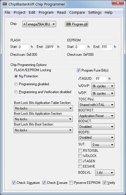
ChipBlasterAVR
A Universal In-System Programming Software for the Microchip AVR family of microcontrollers
Compatible with most AVR development tools
Supports projects
Supports all AVR microcontrollers
This product includes 1 year of free updates and e-mail technical support.
After this period you can purchase 'ChipBlasterAVR Support' to continue to receive free updates and support.
Application that runs under Windows® XP, Vista, Windows 7, 8 and 10, 32-bit and 64-bit
Works with USB, serial port (COM) and parallel port (LPT) based programmers
Loads and saves ELF production files, Intel HEX fiels and binary files
Allows visualizing and editing the contents of the FLASH, EEPROM, lock and fuse bytes
Support for projects, allowing easy one button programming of AVR devices.
Fully compatible with CodeVisionAVR projects, allows executing the programming tasks specified in CodeVisionAVR’s Project|Configure|After Build menu. Ideal for production environments.
Unzip the downloaded file in a temporary directory
Run setup.exe to install.
Note: When installing CodeVisionAVR under Windows Vista, the User Account Control (UAC) must be disabled, as outlined below:
press the Windows button and click on the Control Panel link
in the Control Panel window, under the User Accounts and Family Safety, click on the Add or remove user accounts link
a new window will open, click on the Go to the main User Accounts page link located at the bottom of the window
a new window will open, click on the Turn User Account Control on or off link located at the bottom of the window
in the new window that will open, uncheck the Use User Account Control (UAC) to help protect your computer check box and press the OK button to confirm
the computer will have to be restarted for this setting to become effective.
After UAC has been disabled, you may proceed with the ChipBlasterAVR installation:
run the ChipBlasterAVR installer
after the installation is complete, right click on the ChipBlasterAVR icon on the desktop
select Properties in the popup menu that will open
a new window called ChipBlasterAVR Properties will open
select the Compatibility tab
check the Privilege Level|Run this program as an administrator check box and press the OK button to confirm.
YOUR WEBSHOP CART
Fill in the Form - Check Your Cart - Pay - Enjoy CodeVisionAVR
No VAT is charged unless you are a Belgian customer or a EU customer without a VAT number.
If the automated VAT system fails we will check VAT manually after your purchase and refund the paid VAT.
Your creditcard will always be charged in Euro. Prices in other currencies are indicative.
The Pay button is only available after you filled in all required fields.
×
CodeVisionAVR FAQ
How will I receive my license?
You will receive your download link, install pasword and license ID, with a delay that may be up to 12 hours, from HP Info Tech by e-mail. Please also check your e-mail clients Junk folder as the e-mail might end up there. If you ordered the development kit, the hardware will be shipped to you and you will get shipment information.
How can I download CodeVisionAVR?
You can try the product before purchasing by downloading the CodeVisionAVR Evaluation V4.06: Free, 4kbytes code size limited version. PCF8563, PCF8583, DS1302, DS1307, DS2430, DS2433 libraries are not included. Includes also the Evaluation version of the LCD Vision font editor, with disabled saving of the generated font C source code.
The paid version can be downloaded @ CodeVisionAVR V4.06. This version does require an activiation code which is send to you after your purchase. This commercial version also includes the full LCD Vision font editor. The Advanced license is required to use LCD Vision and the color graphic TFT LCD libraries.
Where can I find the CodeVisionAVR User Manual?
Just download it: cvavrman.zip
How do I setup the software?
CodeVisionAVR V3 is designed to be used both in its own IDE and also as an Extension in Atmel Studio 7 or the older 6.2.1563. It is compatible with all Windows® versions down to XP. For the Atmel Studio Extension to be installed correctly, Atmel Studio must be already present on the computer, before the CodeVisionAVR installer is launched.
Note that while installing and using CodeVisionAVR you must be logged in as Administrator.
You must uninstall any Atmel Studio version older then 6.2.1563 and remove all remaining files in C:\Program Files (x86)\Atmel BEFORE running the CodeVisionAVR installer.
I get a warning from my virus scanner while installing CodeVisionAVR !
CodeVisionAVR is protected by WinLicense from Oreans Technologies. This protection may trigger false alarms in some antivirurses like BitDefender, ESET, AVAST or AVG, preventing CodeVisionAVR from being executed. In such cases you need to add the whole CodeVisionAVR installation \BIN folder to the antivirus file
exclusion list.
Is Atmel Studio required?
No it is not. You can use CodeVisionAVR in its own IDE. For debuging you can also use the AVR Studio 4.19 debugger.
I want to use an older version of CodeVisionAVR
All previous versions of CodeVisionAVR can be downloaded, just ask us for the correct download link. Mind you that each version has a different install password. Please keep a record of the install password(s) which we send you. If you've lost your install password feel free to ask us. You can use the contact form.
Will I receive an invoice for my purchase?
Invoices are send by e-mail for all purchases. It might take a few weeks before you receive your invoice.
Privacy
Our shop does not store any information in an online database. That's why you can not use a login and have to enter your invoice data for each purchase. Your address is only used to send you an invoice. Your e-mail address is used by UVee to send you a purchase confirmation, and by HP Info Tech to send you the license. HP Info Tech will store your address to keep track of your license. On simple request (use the contact form below) UVee will erase all your data, or send you a copy of all your data records.
While using this webshop cookies are used to store your webshop data temporarily on your computer.
Payment with Stripe versus PayPal
Our new webshop uses the services of Stripe to handle your payments. Stripe supports all common creditcards, but also Apple Pay and Google Checkout in selected regions. It also supports local bank cards (region dependant). PayPal recently changed their payment system which resulted in higher costs for both you and us.
What about shipping costs?
CodeVisionAVR and ChipBlasterAVR are download only products, no shipping costs are charged.
All other products are shipped with bPost (first class Mail) and we charge €9.90 for EU destinations and €19.90 for all other destinations. You will get a tracking number once your order has been shipped. Shipping time varies depending on the location, EU destinations usually arrive within 5 working days. Longer distance shipments might take longer. If you want us to send your order with your preferred carrier (on your account), add your carrier account number in the comment field, we'll refund you the charged shipping costs.
Are there any export restrictions
We do not sell to residents of Iran, North Korea, and Russian companies with military subsidaries
CONTACT
Lets get in touch. Send us a message.
Our Company
UVee, originally launched in 1994, has quickly established itself as an innovative and dynamic company. Our main offices are located in Leuven, near the Belgian capital of Brussels. We provide high quality engineering and consulting services for embedded electronics, build and distribute UV Therapy Systems for treatment of skin disorders, and recently launched our new KartTracker kart race timing system. We also maintain a Tesla logging system.